
This instruction show the guide on how to remove and replace loader arms for JCB 3CX 4CX backhoe loader.
Related Contents:
How to use JCB ServiceMaster 4 diagnostic to update aftertreatment ECU software
How to Install JCB Service Master4 Diagnostic Software
Removal
1 Park the machine on firm level ground. Engage the parking brake and set the transmission to neutral.
2 Remove loader end attachment (such as a shovel) if fitted. If the attachment is hydraulically operated,disconnect attachment hoses and plug/cap immediately. Vent residual hydraulic pressure prior to removing hoses by operating the control levers with the engine switched off.
! WARNING
DO NOT work under raised loader arms unless they are adequately supported by stands and/or slings.
BF 3-1
3 Remove the engine panels, refer to Section 3 Routine Maintenance – Engine Panels.
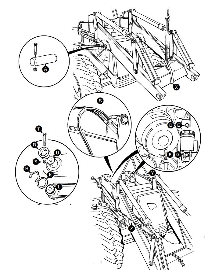
4 Raise the loader arms to give access to the lift ram pivot pins A.
5 Sling the loader arms as shown at X. Make sure that the slings are taut and therefore holding the weight of the loader arms.
6 Switch off the engine and vent residual hydraulic pressure from the loader end by operating the loader controls back and forth several times.
7 Remove the lift ram pivot pins A.
Note: Care must be taken when removing the lift ram pivot pin, once the pin is removed the ram will drop. Either hold the ram using a sling or have a second person hold the ram before removing the pin.
8 Lower the loader arms to the ground using the slings, it may be necessary to retract the lift rams to enable the loader arms to rest fully on the ground. Make sure the lift rams do not foul when retracted.
9 Make sure residual hydraulic pressure has been vented.
Disconnect the shovel ram and auxiliary (if fitted) hoses, shown at B. Plug and cap the hoses immediately.
10 Disconnect the electrical connections (not shown) to the loader shovel reset switch (if fitted).
11 Remove pivot pin retaining bolts D, E, F and G.
12 Sling the loader arms as shown at Y. Make sure that the sling is wrapped around the loader arms only and not the level links.
13 Remove klipring H and shim K.
! WARNING
The loader arm interlevers are potentially dangerous,when pivoting about their centre they form a ‘scissor’ point with the loader arm. Make sure the interlevers are securely blocked when working in the loader arm area.
14 Secure the interlever lever linkage as shown at Z,otherwise with level link pivot pin L removed, the interlever linkage could pivot about its centre and cause injury and/or damage.
15 Remove pivot pin L (use slide hammer kit, service tool 993/68100).
16 Repeat steps 13 to 15 for the opposite level link pivot pin.
17 Remove bolt T and retaining ring R.
18 Remove pivot pin U (use slide hammer kit, service tool 993/68100)
19 Repeat steps 17 and 18 for the opposite loader arm pivot pin.
20 When all four pivot pins have been removed, carefully reverse the machine clear of the loader arms Replacement
Replacement is a reversal of the removal sequence.
Fit pivot pins with the extraction hole on the outside of the machine.
Check operation of loader shovel reset switch (if fitted).
Apply grease to all mainframe bores.
Apply rust inhibiting oil to all pivot pins.
If fitting new liner bearings, assemble with a close fitting shouldered mandrel to ensure minimum ovality
If you want to know more about JCB Electronic Service tool, please visit www.obd2tool.com
Leave a Reply